/ /AluminumCasting /MechContrSyst /ParametricSlicing /AluminumCarving /Thermodynamics /FEA /SPE3Dprinting /ElectricMotorcycle /3dPressureSensingHotend /PopsicleBridge /Ramjet /ModelSterling /3DPrintedDiscGolf /Bonsai /DamascusRing /Drawings /MetropolisFEA /Python /Ceramics
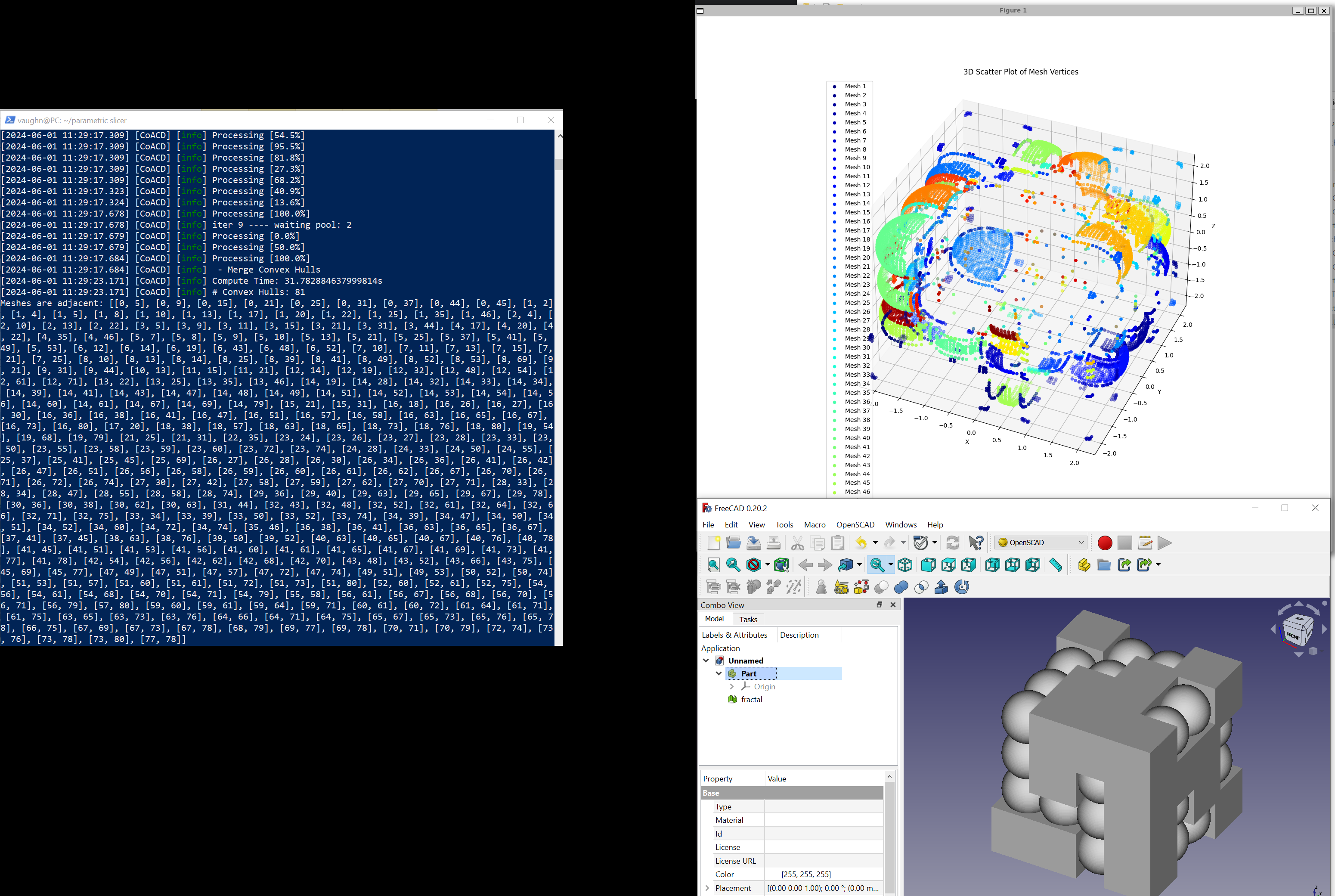
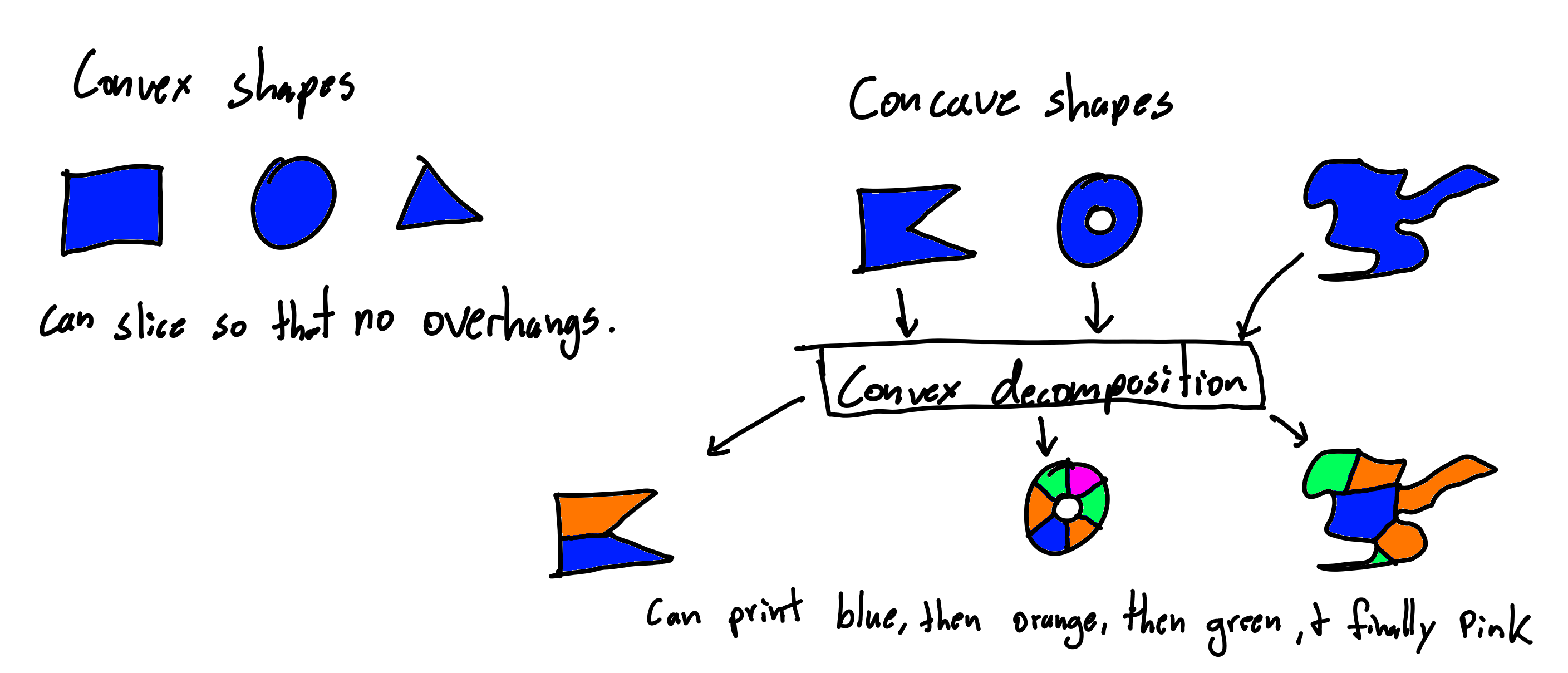
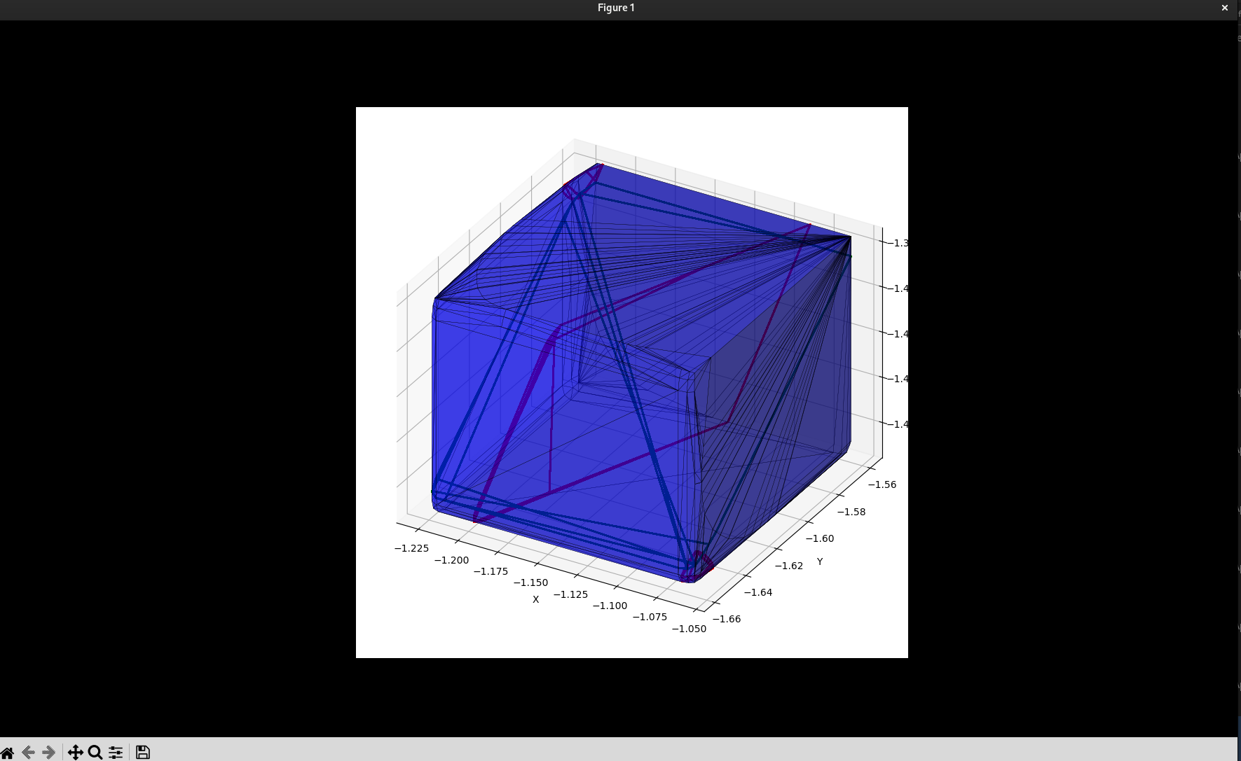
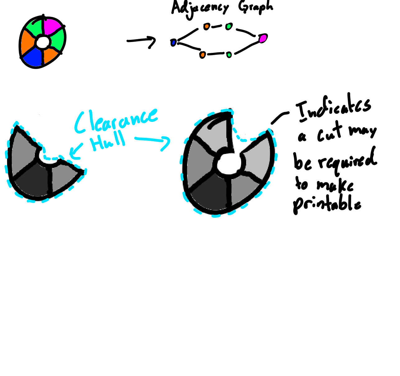
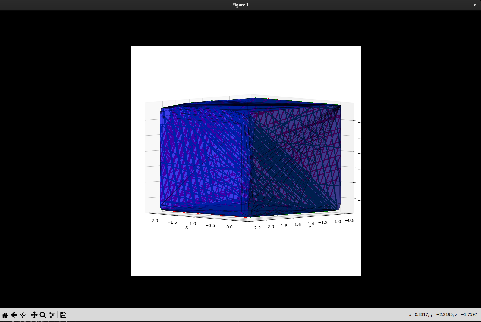
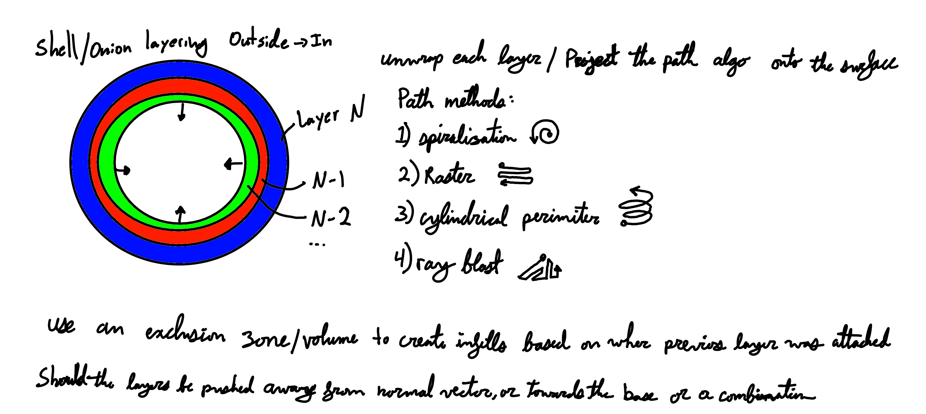
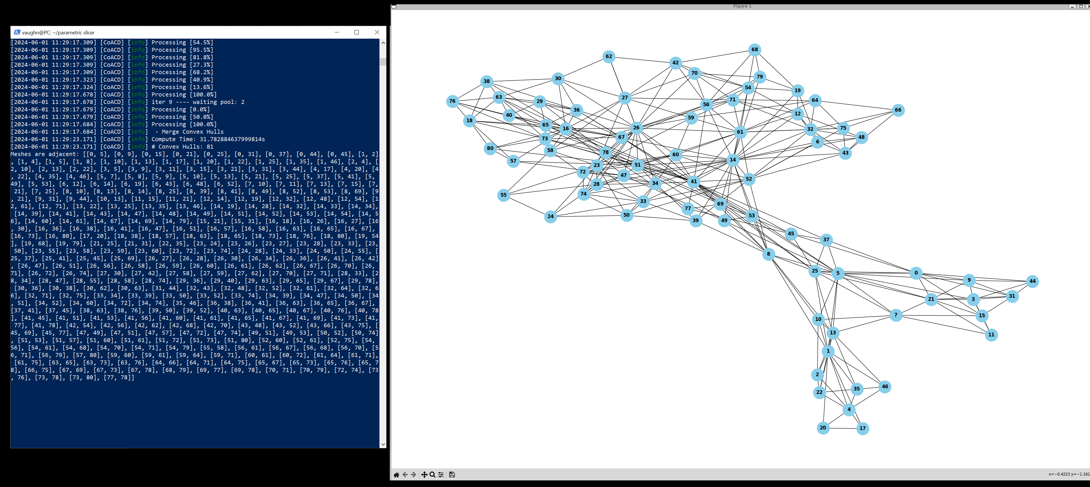
07/04/2023: Here's the idea: 2d slicing for 3d models has limitations in the overhangs that can be done and may limit the speed of the prints to some extent. The other thing is that surface finishes and print strength are highly dependant on the layering of the materials. The solution might be parametric slicing. This is a method of generating printing code that is not in layers, it's 3d paths instead of 2d paths. I'm working on how to do this parametric slicing and think I've got it figured out but just need to implement a first draft. How it will be done. 3 dimensions is a lot of space to cover so we need a way of limiting scope so that the parts that would block others are left for the end of the print. I also want to have minimal overhangs and as good surface finishes as possible. You can achieve this by splitting a model into convex components. Any convex component will necessarly have some slicing method that doesn't have any overhangs. Sooo first split a model into convex components: a Convex Decomposition. It doesn't have to be a perfect Convex decomposition because we can tolerate slight overhangs so we can work with just an Approximate Convex Decomposition. Then select the order of component printing to get as good surfaces as possible and make sure no blocking components are made before the others. (for my first try I'm just worrying about the order of components) then create a path for each of the components and put all the component paths together for the final 3d print path. Hopefully it works? it seems like a novel method of slicing for 3d prints. Here are some pictures of 2d then 3d verification of the process. 07/13/2023: So here it is. I think I've figured out how to determine if anything needs to be done before other operations: Since we are using convex hulls in this algorythm already why not use them to get the exclusion area, when chosing the next convex shape to print see if the new convex hull precluded other convex parts. The convex hull is a bit too much and doesnt take into account head clearance for the printer. We can make a clearance hull by shifting the convex hull inwards by a set or variable amount to account for the clearance of the printer. The end shape is a convex hull that has the faces curved inwards. Also we make an adjacency graph of the convex parts. with this graph we can determine a decently fast path to print through. What parts of the graph are ends and what the ordering needs to be from an initial point. Find the parts of the graph that have the most dead ends and use that as the default print base. To get a first approximation you can just move the convex hull inwards progressively by the clearance angle on the print head. to get an exact soultion I think you would need to do some weird rolling action of the print head... still working on that one as of yet. 07/05/2024: I have been doing some work on this, You can find some videos I made on this on youtube at: https://www.youtube.com/@vaughnanderson7984 (no real URLs here lol) I have the approximate Convex decomposition and graph creation working. Now I am working towards creating paths for each of the decompositions. I am going to be taking each mesh of the decomposition and creating successive layers/sheets around the previous layer. So it is creating layers like an onion from the outside towards the inside. The algorithm will move each layer away from the normal vector of the suface or towards the base/ground plane of that mesh or it might end up being a combination between the two... The infill patterns can be created with exclusion zones/volumes inside the part and then touching points close to previous layers path. Here are a few path mapping algos that I could move onto the surface: 1. Spiralization, moving from a point outwards in a continuos arc or whatever path is closest to a spiral. 2. Line scan/Raster, scan back and forth linearly mapped onto the surface. 3. Cylindrical Perimeter, go around the perimiter of the part and build up that way. 4. ray blast, path out from a certain point as close to rays emminating from the start point. One of the major issues I think I might encounter when getting the g-code generated is that the files might be massive with linear interpolation to each point... Will tackle that only if it is a real problem. Additionally in the videos I am having trouble finding a good way of choosing the path allong the nodes of each mesh in the print. I am trying to choose an initial node and expand outwards but that seems to be causing issues. Maybe a better way of growing outwards is to grow backwards from the outside towards a base mesh? Maybe by removing one node at a time that has maximizing the change to the volume of the convex hull and chose the nodes along the node graph such that distance away from the selected base mesh is prioritized. We shall see. Now I just need to do the hard work of implementing the pathing... I wonder if there is a python library I can force to do the hard work for me... 08/01/2024: I have the path algorithm mostly done and additionally I have a method of slicing the submesses completed. You can see two images of a submesh that is sliced around the the part by finding the intersections between the mesh and 2 series of planes. The larger one with more lines is at its largest size and the smallest one is at its smallest limit. So what happens is the mesh starts at a the decomposed mesh and then sliced, The mesh is then scaled in the direction of the "grounded vector" and regular scaling by the layer height then resliced. The actual paths are all put together backwards from the smallest to the largest like an onion build up from a base. Also the direction of the nozzle is calculated at this point and in the simple method I am doing is just the negative of the normal vector of the triangle that was intersected by the plane. All this is saved as X0, Y0, Z0, A0, B0, C0, X1, Y1, Z1, A1, B1, C1 being the two points on each end of the line with the associated required nozzle direction. This can easily be converted directly to gcode for an individual machine. All the different intersections from the onion method of each decomposed meshes are then concatinated based on the order determined by our algorithm.(Some rapid may be needed between the meshes) The next step for me is to animate the layers being added in blender. Lots of shortcuts were taken so this is not going to be a final product, more of a proof of concept. Things are getting exciting.
email: va.web.code@gmail.com https://github.com/va-code https://www.youtube.com/@vaughnanderson7984