July 4, 2023
Here's the idea: 2d slicing for 3d models has limitations in the overhangs that can be done and may limit the speed of the prints to some extent. The other thing is that surface finishes and print strength are highly dependant on the layering of the materials. The solution might be parametric slicing. This is a method of generating printing code that is not in layers, it's 3d paths instead of 2d paths. I'm working on how to do this parametric slicing and think I've got it figured out but just need to implement a first draft.
How it will be done. 3 dimensions is a lot of space to cover so we need a way of limiting scope so that the parts that would block others are left for the end of the print. I also want to have minimal overhangs and as good surface finishes as possible. You can achieve this by splitting a model into convex components. Any convex component will necessarly have some slicing method that doesn't have any overhangs.
Sooo first split a model into convex components: a Convex Decomposition. It doesn't have to be a perfect Convex decomposition because we can tolerate slight overhangs so we can work with just an Approximate Convex Decomposition. Then select the order of component printing to get as good surfaces as possible and make sure no blocking components are made before the others. (for my first try I'm just worrying about the order of components) then create a path for each of the components and put all the component paths together for the final 3d print path.
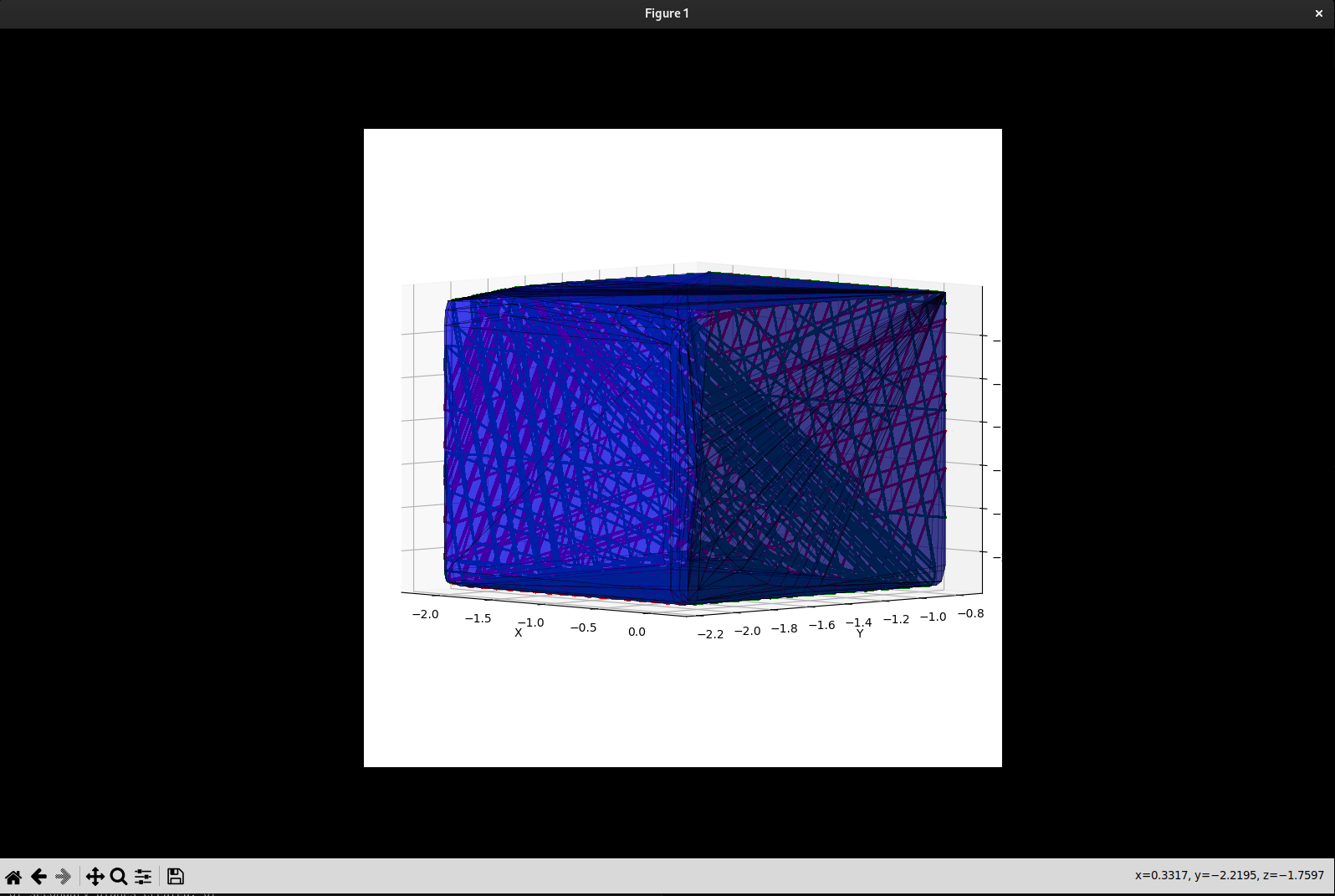
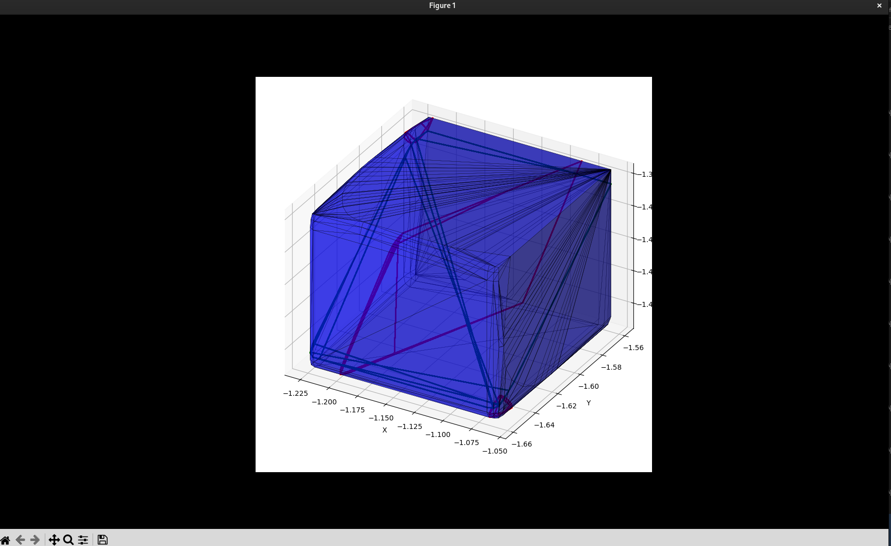
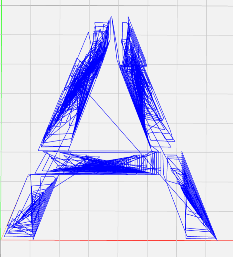
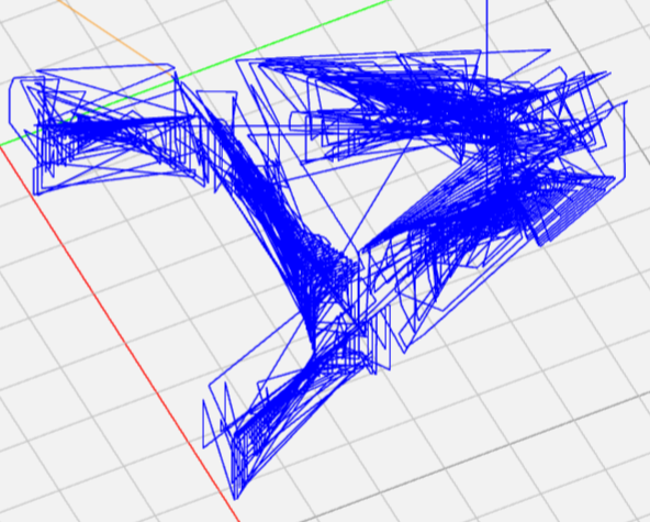
Hopefully it works? it seems like a novel method of slicing for 3d prints. Here are some pictures of 2d then 3d verification of the process.
July 13, 2023
So here it is. I think I've figured out how to determine if anything needs to be done before other operations:
Since we are using convex hulls in this algorythm already why not use them to get the exclusion area, when chosing the next convex shape to print see if the new convex hull precluded other convex parts. The convex hull is a bit too much and doesnt take into account head clearance for the printer. We can make a clearance hull by shifting the convex hull inwards by a set or variable amount to account for the clearance of the printer. The end shape is a convex hull that has the faces curved inwards.
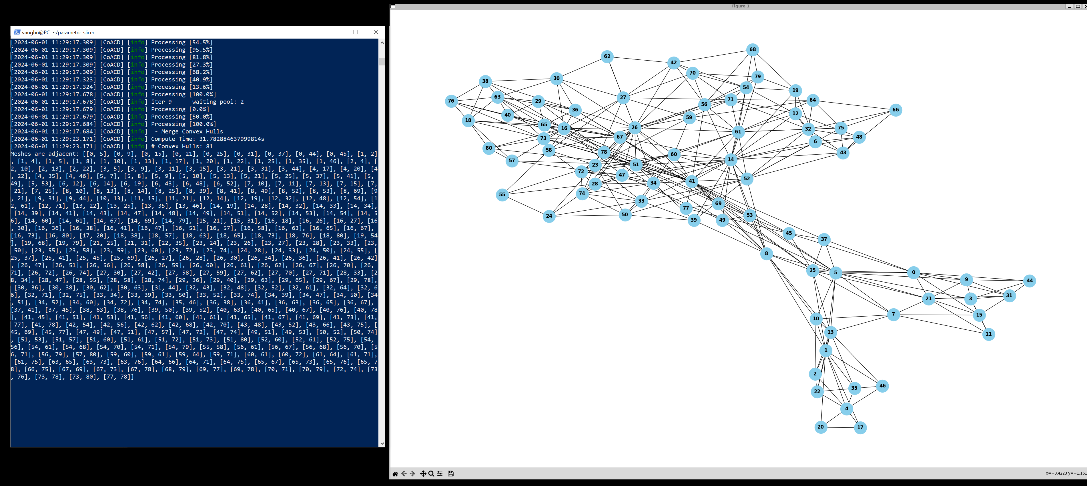
Also we make an adjacency graph of the convex parts. with this graph we can determine a decently fast path to print through. What parts of the graph are ends and what the ordering needs to be from an initial point. Find the parts of the graph that have the most dead ends and use that as the default print base.
To get a first approximation you can just move the convex hull inwards progressively by the clearance angle on the print head. to get an exact soultion I think you would need to do some weird rolling action of the print head... still working on that one as of yet.